
1. What Is Optical System Design?
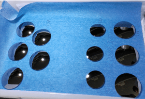
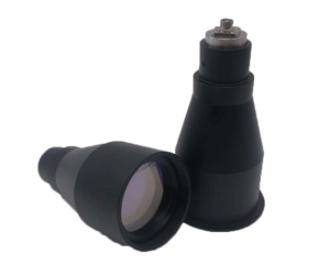
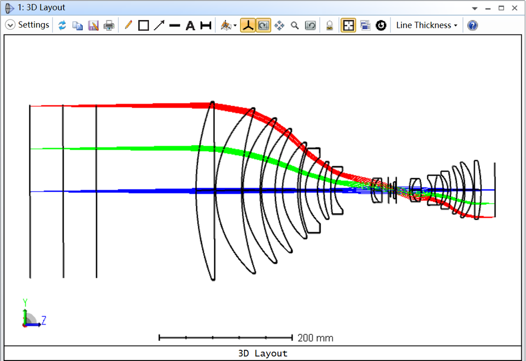
Optical system design is the engineering process of developing an optical arrangement that controls how light travels, interacts with optical components, and reaches a target or detector. It involves selecting and optimizing lenses, mirrors, prisms, filters, windows, and other optical elements to achieve specific performance requirements.
An optical system can be designed for image formation, laser beam delivery, illumination, sensing, spectroscopy, or other applications where precise control of light is essential.
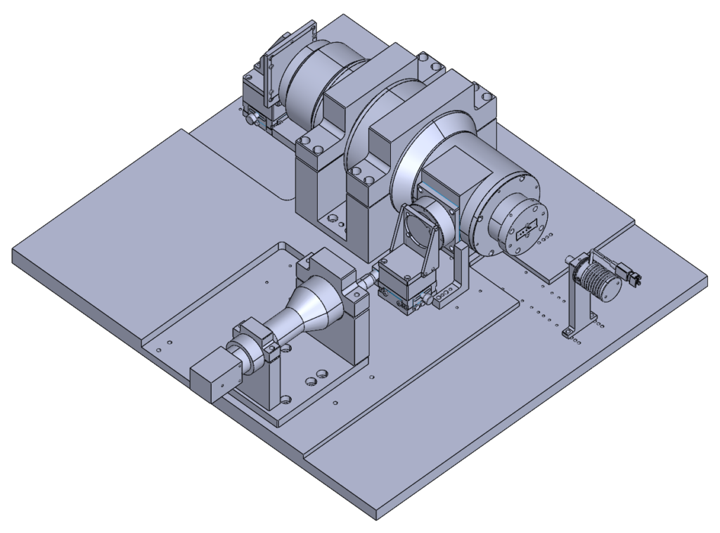
Unlike designing an individual lens, optical system design considers the performance of the complete optical assembly. Engineers must evaluate how each component interacts with the others, including optical alignment, mechanical mounting, thermal effects, manufacturing tolerances, and environmental conditions.
A high-performance optical system typically requires a combination of:
- Optical design and ray tracing.
- Lens and mirror selection.
- Optical material evaluation.
- Aberration correction.
- Optical simulation and optimization.
- Opto-mechanical integration.
- Manufacturing tolerance analysis.
- Optical testing and system validation.
Today, optical system design is essential in industries such as aerospace, defense, medical imaging, semiconductor inspection, machine vision, laser processing, telecommunications, and scientific instrumentation.
At BOTE Optics, we combine optical engineering, precision component manufacturing, optical coating, and opto-mechanical integration to support customized optical projects, from individual optical elements to complex lens assemblies.
2. What Is Optics? Understanding the Fundamentals
Optics is the branch of physics that studies the behavior of light, including its generation, propagation, reflection, refraction, diffraction, and interaction with materials.
Understanding optics is the foundation of optical system design. Engineers use several optical principles to predict and control light behavior.
2.1 Geometrical Optics
Geometrical optics treats light as rays traveling along predictable paths. It is commonly used to determine focal length, magnification, image position, field of view, and the basic layout of optical systems.
Snell’s law describes how light changes direction when passing between materials with different refractive indices:
n1 sin(θ1) = n2 sin(θ2)
Where:
- n1 and n2 are the refractive indices of the two materials.
- θ1 is the angle of incidence.
- θ2 is the angle of refraction.
This principle is essential for designing refractive optical components, including lenses and prisms.
2.2 Physical Optics
Physical optics considers the wave nature of light. It is important when diffraction, interference, polarization, and coherence affect system performance.
For high-performance optical systems, engineers may need to evaluate diffraction-limited resolution, wavefront error, and polarization effects in addition to geometrical ray paths.
2.3 Optical Materials
Material selection directly affects optical performance.
Common optical materials include:
- Optical glass: BK7 and other crown and flint glasses.
- Fused silica: Suitable for many UV, visible, and NIR applications.
- Calcium fluoride (CaF2): Used in UV and infrared optical systems.
- Germanium (Ge): Widely used in MWIR and LWIR optics.
- Zinc selenide (ZnSe): Common in infrared laser and thermal imaging applications.
- Zinc sulfide (ZnS): Used in infrared imaging and protective optical windows.
- Silicon (Si): Used in infrared optics and semiconductor-related applications.
- Sapphire: Offers high hardness and excellent environmental durability.
The appropriate material depends on the operating wavelength, refractive index, dispersion, transmission, thermal properties, and manufacturing requirements.
Share with you a very helpful Optical Glass Grade Comparison Table
3. What Do Optical Engineers Do?
Optical engineers translate system requirements into practical optical designs that can be manufactured, assembled, and tested.
Their responsibilities extend beyond designing lenses. They must understand how the complete system performs under real operating conditions.
Typical responsibilities include:
System Requirement Analysis
Define focal length, aperture, field of view, wavelength range, image quality, working distance, and environmental requirements.
Optical Layout and Lens Design
Select suitable optical configurations and calculate the initial lens and mirror parameters.
Optical Simulation
Use optical design software to perform ray tracing, evaluate aberrations, and predict system performance.
Performance Optimization
Adjust optical surfaces, materials, element spacing, and other variables to improve image quality and meet performance targets.
Opto-Mechanical Engineering
Design lens barrels, mounts, spacers, and mechanical interfaces to maintain optical alignment and stability.
Manufacturing and Quality Control
Translate optical prescriptions into manufacturing drawings, tolerances, assembly instructions, and inspection requirements.
A successful optical engineer must understand both theoretical optics and practical manufacturing limitations.
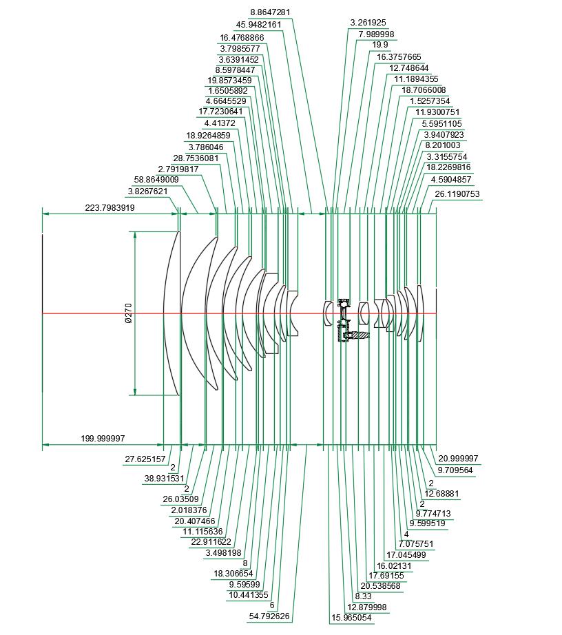
4. How to Design an Optical System: A Step-by-Step Process
Optical system design should always start with the application and its performance requirements, rather than selecting lenses immediately.
The following workflow provides a practical approach to developing a precision optical system.
Step 1: Start With the Requirements for the System
The first step is to establish a complete set of system requirements.
Before beginning the design, engineers should identify:
- Intended application.
- Operating wavelength or spectral range.
- Effective focal length (EFL).
- Clear aperture.
- F-number or numerical aperture (NA).
- Field of view (FOV).
- Object distance and image distance.
- Required magnification.
- Image sensor size and pixel pitch, if applicable.
- Working distance.
- Resolution and MTF requirements.
- Operating temperature and environmental conditions.
- Mechanical dimensions and weight limitations.
- Target manufacturing cost.
For example, a thermal imaging system operating in the 8–12 μm LWIR band requires different optical materials and coatings from a visible-light camera.
Similarly, a high-power laser focusing system requires special consideration of laser damage threshold, coating absorption, thermal loading, and surface quality.
A clearly defined specification reduces unnecessary design changes and helps engineers select the most appropriate optical architecture.
Step 2: Analyze the Optical System Needs
Once the requirements are established, the next step is to determine the most suitable optical configuration.
Different applications require different optical structures.
| Optical System | Main Design Objective | Typical Applications |
|---|---|---|
| Imaging System | Image quality, resolution, and distortion control | Cameras, microscopes |
| Laser Optical System | Beam focusing, collimation, and energy delivery | Laser processing |
| Infrared Optical System | Spectral transmission and thermal imaging | Surveillance, thermal cameras |
| Telecentric System | Stable magnification and low perspective error | Metrology, inspection |
| Afocal System | Angular magnification and collimated output | Telescopes, beam expanders |
| Illumination System | Uniformity and light distribution | Machine vision, lighting |
| Spectroscopic System | Wavelength separation and measurement | Scientific instruments |
Engineers should also determine whether the system needs refractive optics, reflective optics, or a combination of both.
For example:
- Refractive systems use lenses to control light through refraction.
- Reflective systems use mirrors to redirect and focus light.
- Catadioptric systems combine lenses and mirrors to achieve specific optical configurations.
The best architecture depends on performance, size, weight, cost, wavelength, and manufacturing constraints.
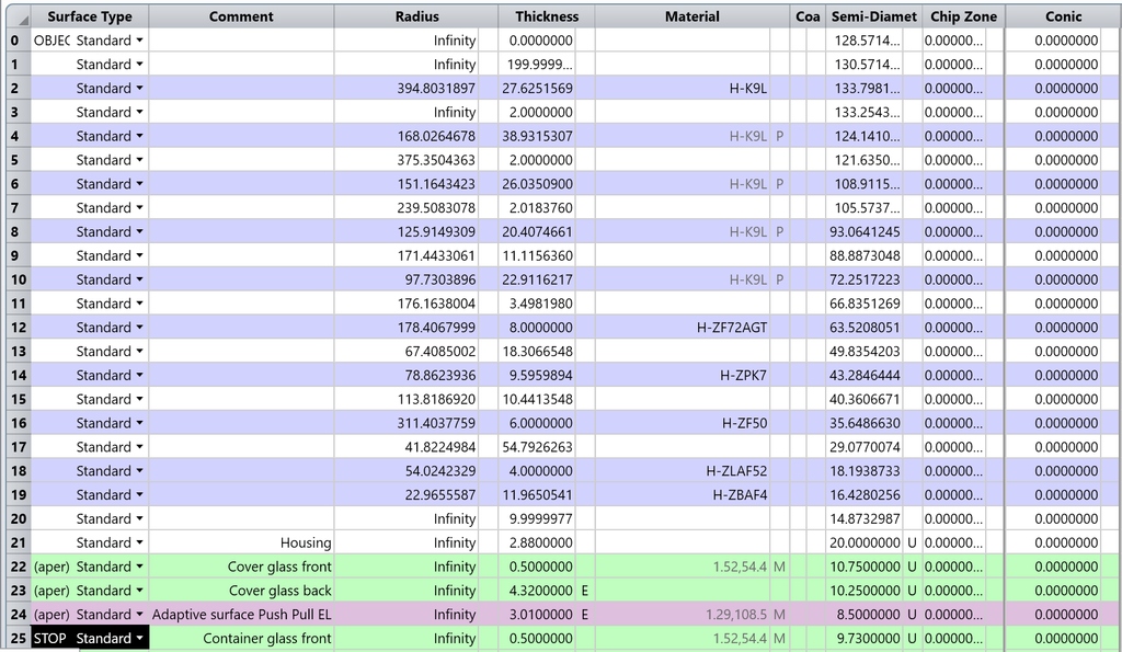
Step 3: Perform First Order Optical System Design
First-order optical system design, also known as paraxial design, establishes the basic optical layout before detailed optimization.
It focuses on fundamental parameters such as:
- Effective focal length.
- Image distance.
- Object distance.
- Magnification.
- Aperture and F-number.
- Field of view.
- Entrance and exit pupils.
- Principal planes.
For a simple thin-lens system, the lens equation is:
1/f = 1/do + 1/di
Where:
- f = Focal length.
- do = Object distance.
- di = Image distance.
The lateral magnification is:
m = −di/do
These equations provide a starting point for determining image formation and establishing the initial optical layout.
However, real optical systems often contain multiple elements, finite thicknesses, complex surface geometries, and non-paraxial ray behavior. Detailed optical design software is therefore required for further analysis.
Step 4: Use Lens Starting Point Resources
Building a complex optical system from scratch can be time-consuming.
Optical designers often use existing lens designs, catalog optics, and established optical configurations as starting points.
Useful resources include:
Commercial Lens Catalogs
Manufacturers such as Edmund Optics, Thorlabs, and other optical suppliers provide standard lenses, mirrors, filters, and optical assemblies.
Catalog components can help engineers build an initial optical layout and evaluate whether standard optics can satisfy the system requirements.
Existing Lens Design Forms
Common optical configurations include:
- Double Gauss lenses.
- Cooke triplets.
- Tessar lenses.
- Telephoto lenses.
- Retrofocus lenses.
- Petzval lenses.
- Cassegrain and Gregorian reflective systems.
Each configuration has different advantages and limitations.
Optical Design Libraries
Optical design software and technical publications provide useful starting points for lens construction, material selection, and system optimization.
Starting with a proven configuration can reduce development time, but engineers must still verify the design against the actual system requirements.
5. Lenses and Lens Designers: How to Design a Lens
Lenses are fundamental building blocks of many optical systems. They control light through refraction and are used to focus, collimate, magnify, or reduce images.
A lens designer must consider more than focal length. The design must balance image quality, aberration correction, optical transmission, mechanical size, and manufacturability.
5.1 Select the Lens Configuration
Common lens types include:
- Plano-convex lenses.
- Bi-convex lenses.
- Plano-concave lenses.
- Bi-concave lenses.
- Achromatic doublets.
- Aspherical lenses.
- Cylindrical lenses.
- Meniscus lenses.
- Fresnel lenses.
For example, an aspherical lens can provide additional control over spherical aberration and may reduce the number of elements needed in a compact optical system.
An achromatic doublet combines two materials with different dispersion characteristics to reduce chromatic aberration.
A cylindrical lens focuses light in one principal axis and is commonly used in laser beam shaping.
5.2 Choose the Optical Materials
Material selection is a critical part of lens design.
The designer must evaluate refractive index, Abbe number, partial dispersion, transmission range, thermal expansion, and material availability.
For infrared systems, optical materials such as germanium, silicon, zinc selenide, zinc sulfide, and calcium fluoride may be considered according to the wavelength range.
For UV and visible systems, fused silica and suitable optical glasses are common choices.
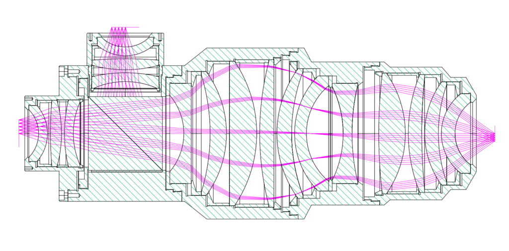
5.3 Define Surface Geometry
The optical prescription specifies the geometry and arrangement of each optical surface.
Important parameters include:
- Surface radius of curvature.
- Center thickness.
- Air spacing.
- Conic constant.
- Aspherical coefficients.
- Clear aperture.
- Surface orientation.
The prescription defines the optical geometry required to achieve the target system performance.
5.4 Evaluate Image Quality
Lens designers use several metrics to evaluate performance.
Spot Diagram: Shows the distribution of traced rays at the image plane.
Modulation Transfer Function (MTF): Describes how well an optical system transfers image contrast at different spatial frequencies.
Wavefront Error: Measures deviations of the optical wavefront from an ideal reference wavefront.
Distortion: Measures changes in image geometry.
Relative Illumination: Evaluates how image brightness changes across the field.
These measurements help engineers determine whether a lens design meets the required imaging performance.
6. Overcoming Obstacles: Optical Aberrations
Optical aberrations are deviations from ideal image formation. They can reduce resolution, contrast, and image accuracy.
A high-performance optical design must identify and control the aberrations that matter most to the application.
6.1 Spherical Aberration
Spherical aberration occurs when rays passing through different zones of a spherical lens focus at different axial positions.
It can be reduced through appropriate lens bending, aspherical surfaces, and multi-element optical configurations.
6.2 Chromatic Aberration
Chromatic aberration results from wavelength-dependent refractive index changes.
It causes different wavelengths to focus at different positions.
Achromatic and apochromatic lens designs help reduce this effect.
6.3 Coma
Coma causes off-axis point sources to appear asymmetric, often with a comet-like shape.
It is important in wide-field imaging systems and can be controlled through optical configuration, stop position, and surface optimization.
6.4 Astigmatism
Astigmatism occurs when tangential and sagittal rays focus at different positions.
It can reduce image sharpness away from the optical axis.
6.5 Field Curvature
Field curvature causes the best-focus image surface to become curved instead of flat.
Plan lenses and specially optimized multi-element systems can help correct this issue.
6.6 Distortion
Distortion changes the geometric position of image points without necessarily reducing local image sharpness.
It is especially important in metrology, machine vision, and measurement systems.
The appropriate aberration correction strategy depends on the optical system’s field of view, aperture, wavelength, and image quality requirements.
7. How Deep Is My Valley? Optical Design Optimization
Optical optimization is one of the most challenging stages of optical system design.
The goal is to find a set of optical parameters that produces the required system performance while satisfying mechanical, manufacturing, and cost constraints.
In numerical optimization, the performance landscape can be imagined as a valley.
The bottom of the valley represents a solution with a low merit function value. However, optical systems often contain many local minima, meaning an optimizer may find a satisfactory solution without finding the best available design.
This is why optical designers must understand both the optimization process and the physical behavior of the system.
7.1 Define the Merit Function
A merit function mathematically evaluates how well a design meets its target requirements.
It may include:
- Spot size.
- MTF.
- Wavefront error.
- Focal length.
- Distortion.
- Chromatic correction.
- Relative illumination.
- Mechanical constraints.
The designer assigns appropriate weights to each requirement according to its importance.
For example, a high-resolution imaging system may prioritize MTF and wavefront performance, while a laser beam delivery system may prioritize beam quality and focal position.
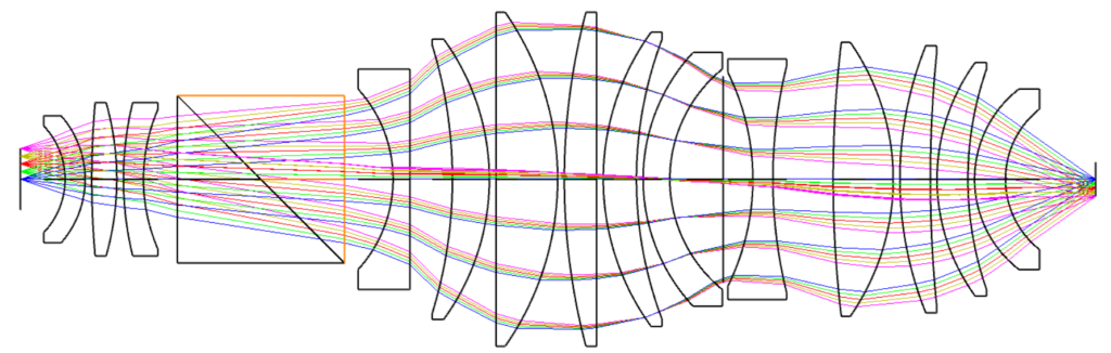
7.2 Select Variables and Constraints
Variables are parameters that the optimization algorithm can adjust.
Typical variables include:
- Surface curvature.
- Lens thickness.
- Air spacing.
- Glass selection.
- Aspherical coefficients.
- Stop position.
Constraints prevent the optimizer from producing physically unrealistic solutions.
For example, the designer may restrict lens thickness, edge thickness, element diameter, air spacing, or manufacturing complexity.
7.3 Local and Global Optimization
Local optimization improves a design using the current solution as a starting point.
Global optimization explores a broader design space to identify alternative solutions that may provide better performance.
In practical optical engineering, designers often combine different optimization strategies, manual adjustments, and engineering judgment.
7.4 Design for Manufacturing
An optical design should not only perform well in simulation. It must also be manufacturable.
A design with extremely tight surface tolerances or complex alignment requirements may become too expensive or difficult to produce.
Therefore, tolerance analysis should be included before the design is finalized.
The most effective optical system is not necessarily the one with the lowest theoretical aberration. It is the one that consistently achieves the required performance after manufacturing and assembly.
8. Advanced Optical Design Software for Precision Engineering
Modern optical design software allows engineers to model, simulate, analyze, and optimize complex optical systems before manufacturing begins.
Optical simulation software is used to reduce development risks, compare design alternatives, and predict how an optical system will perform under different operating conditions.
8.1 Common Optical Design Software
The following is a practical overview of widely used optical engineering software.
| Software | Main Functions | Typical Applications |
|---|---|---|
| Ansys Zemax OpticStudio | Sequential and non-sequential optical design, ray tracing, optimization, tolerancing | Imaging, laser, illumination |
| Synopsys CODE V | Lens design, optimization, aberration analysis, tolerancing | High-performance imaging |
| OSLO | Optical system layout, lens design, analysis, optimization | General lens design and education |
| FRED | Optical simulation, stray-light analysis, illumination and non-sequential ray tracing | Laser and illumination systems |
| LightTools | Illumination simulation and optimization | Lighting, displays, backlighting |
| TracePro | Non-sequential ray tracing and stray-light analysis | Illumination and optical engineering |
| SolidWorks | Mechanical CAD and opto-mechanical integration | Lens barrels, housings, mounts |
| MATLAB | Numerical analysis, modeling, and engineering calculations | Optical analysis and custom algorithms |
These tools serve different purposes. Some focus on image-forming lens systems, while others specialize in illumination, stray light, mechanical integration, or numerical analysis.
8.2 Ansys Zemax OpticStudio
Ansys Zemax OpticStudio is widely used for optical system design, lens optimization, and performance analysis.
It supports sequential and non-sequential modeling, ray tracing, optical optimization, tolerancing, and system evaluation.
Engineers can use it to design camera lenses, microscope objectives, infrared optical systems, laser assemblies, and other precision optical instruments.
Official website: https://www.ansys.com/products/optics/zemax-opticstudio
8.3 Synopsys CODE V
CODE V is a professional optical design platform used for high-performance imaging systems.
Its capabilities include lens optimization, optical analysis, glass selection, and manufacturing tolerance evaluation.
It is particularly relevant to demanding imaging applications where optical performance and production feasibility must be evaluated together.
Official website: https://www.keysight.com/us/en/products/design-engineering-software/optical-design-engineering/optical-design-software-code-v.html
8.4 OSLO and Other Optical Simulation Tools
OSLO is another established optical design platform used for lens layout, optical analysis, and educational purposes.
FRED, LightTools, and TracePro are useful when the engineering task involves non-sequential ray tracing, illumination, stray light, or complex light distribution.
The best optical simulation software depends on the type of system, analysis requirements, engineering workflow, and available budget.
8.5 Why Optical Simulation Matters
Optical simulation helps engineers identify performance limitations before expensive physical prototypes are produced.
It can be used to:
- Predict image quality.
- Analyze optical aberrations.
- Evaluate material combinations.
- Optimize lens geometry.
- Estimate system transmission.
- Study stray light.
- Evaluate manufacturing tolerances.
- Support mechanical integration.
However, simulation results must be validated through physical measurement. A virtual design cannot fully replace optical fabrication, assembly, alignment, and testing.
9. Optical Design Drawings: From Optical Prescription to Manufacturing
An optical design drawing is the technical document that communicates the requirements of an optical component or assembly to the manufacturer.
A theoretical optical prescription is not sufficient for production. The drawing must define the geometry, tolerances, material, surface quality, coating, and inspection requirements.
A typical optical design drawing may include:
| Drawing Parameter | Description |
|---|---|
| Material | Optical glass, fused silica, Ge, ZnSe, CaF2, etc. |
| Diameter | Overall mechanical diameter |
| Clear Aperture | Usable optical area |
| Radius | Surface radius of curvature |
| Center Thickness | Thickness at the optical center |
| Surface Figure | Surface form accuracy |
| Surface Quality | Scratch-dig specification |
| Centration | Optical axis alignment requirement |
| Wedge | Angular deviation between surfaces |
| Coating | AR, HR, DLC, ITO, or other coatings |
| Edge Treatment | Chamfer and edge specifications |
| Tolerances | Dimensional and optical tolerances |
ISO 10110 is an important international standard series for preparing technical drawings of optical elements and systems.
The drawing should also define the inspection method and acceptance criteria wherever necessary.
For complex optical assemblies, engineers may need additional documents, including:
- Lens assembly drawings.
- Mechanical interface drawings.
- Optical alignment specifications.
- Bill of materials.
- Inspection reports.
- Coating specifications.
Accurate drawings help reduce misunderstandings between optical designers, manufacturers, and assembly engineers.
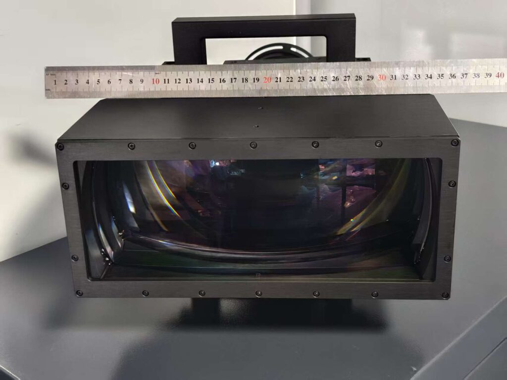
10. Opto-Mechanical Design: Connecting Optics and Mechanical Engineering
Opto-mechanical design is the integration of optical components with mechanical structures.
An optical system can perform well in simulation but fail after assembly if the mechanical design introduces excessive stress, tilt, decenter, or thermal instability.
Important opto-mechanical considerations include:
Mechanical Alignment
Lens and mirror positions must be controlled relative to the system optical axis.
Thermal Stability
Changes in temperature can affect the dimensions of optical mounts, lens spacing, and refractive indices.
Material Compatibility
The thermal expansion properties of optical materials and mechanical structures must be considered together.
Mounting and Retention
Optical elements must be held securely without introducing excessive stress or deformation.
Assembly and Testing
The mechanical design should allow practical alignment, inspection, and maintenance.
Opto-mechanical engineering is especially important in aerospace, defense, infrared imaging, precision measurement, and high-performance laser systems.
11. SPIE Optical System Design: Professional Knowledge and Industry Development
SPIE, the international society for optics and photonics, is an important professional organization for optical engineers, scientists, and photonics researchers.
Its technical conferences, publications, exhibitions, and professional courses provide opportunities to learn about developments in optical system design and engineering.
Relevant technical topics include:
- Lens design and optimization.
- Optical system layout.
- Infrared optical engineering.
- Optical metrology.
- Opto-mechanical design.
- Optical manufacturing.
- Laser system engineering.
- Imaging and sensing technologies.
SPIE courses such as Introduction to Lens Design and Practical Optical System Design provide structured learning opportunities for professionals who want to improve their understanding of optical engineering.
SPIE’s technical conferences also help engineers exchange practical knowledge and explore new technologies.
For optical manufacturers, participation in professional organizations provides opportunities to connect with researchers, system developers, and customers across the global photonics industry.
Learn more: https://www.spie.org/
12. Optical Design Courses and Learning Resources
Optical system design combines physics, mathematics, software skills, and practical engineering experience.
Students and engineers who want to develop their skills can choose from university programs, professional short courses, textbooks, and software tutorials.
12.1 Optical Design Courses
An optical design course typically covers:
- Geometrical optics.
- First-order optical system design.
- Lens design principles.
- Optical aberrations.
- Ray tracing.
- Optical simulation.
- Image quality analysis.
- Optimization techniques.
- Manufacturing tolerances.
A good course should include practical design exercises rather than focusing only on theoretical equations.
12.2 Opto-Mechanical Design Courses
An opto-mechanical design course focuses on the mechanical aspects of optical system integration.
Topics may include:
- Mechanical properties of optical materials.
- Lens mounting and retention.
- Optical alignment.
- Thermal and structural analysis.
- Mechanical tolerances.
- Assembly and testing.
These skills are essential for engineers responsible for taking optical designs from simulation to working hardware.
12.3 Institute of Optics Summer School
The Institute of Optics at the University of Rochester offers professional summer short courses covering optical system design, lens design, optical engineering, and opto-mechanical design.
Its educational programs include practical topics such as first-order optical layout, image quality evaluation, aberration theory, optimization, optical design software, and tolerance analysis.
These courses can be useful for engineers seeking structured professional development.
Course information: https://hajim.rochester.edu/optics/summer/courses.html
12.4 Recommended Optical System Design Books
Books remain valuable resources for understanding the theory behind optical engineering.
Some established references include:
Optical System Design – Robert E. Fischer, Biljana Tadic-Galeb, and Paul R. Yoder Jr.
A comprehensive reference covering optical system design principles, engineering considerations, optimization, and practical design workflows.
Modern Optical Engineering – Warren J. Smith
A widely recognized reference covering optical principles, components, systems, and engineering applications.
Lens Design Fundamentals – Rudolf Kingslake and R. Barry Johnson
A useful reference for understanding lens design principles and optical system development.
Fundamentals of Optics – Eugene Hecht
A foundational textbook covering geometrical optics, wave optics, interference, diffraction, and polarization.
Combining theoretical study with optical design software and practical manufacturing experience provides a stronger foundation than relying on any single learning resource.
13. Design of High-Performance Optical Systems: Key Engineering Challenges
High-performance optical systems require more than achieving a good theoretical image or beam profile.
The final product must maintain its performance after fabrication, coating, assembly, alignment, and environmental exposure.
Several engineering factors deserve particular attention.
13.1 Performance Versus Cost
Increasing optical performance may require more optical elements, tighter tolerances, special materials, and complex coatings.
The design should balance optical performance with manufacturing cost and production feasibility.
13.2 Manufacturing Tolerances
Surface figure, surface roughness, centration, thickness, and wedge can all affect the final optical performance.
A tolerance budget should be established early in the design process.
13.3 Optical Coatings
Coatings can improve transmission, reflection, durability, and spectral selectivity.
The coating design must match the operating wavelength, angle of incidence, polarization, and environmental conditions.
13.4 Thermal and Environmental Stability
Temperature changes may affect refractive index, optical spacing, and mechanical alignment.
For demanding applications, engineers may need athermalization, thermal compensation, and structural analysis.
13.5 Optical Testing and Validation
The finished optical system should be tested against its original specifications.
Depending on the application, testing may include:
- Interferometric surface and wavefront measurement.
- MTF testing.
- Centration measurement.
- Spectral transmission measurement.
- Surface roughness measurement.
- Environmental testing.
- System alignment and performance verification.
Designing for measurable and repeatable performance is essential for high-reliability optical products.
14. Optical System Design and Manufacturing Capabilities at BOTE Optics
BOTE Optics (S) Pte Ltd is a Singapore-based manufacturer specializing in precision optical components, customized lenses, optical coatings, and opto-mechanical solutions.
With more than 20 years of optical industry experience and engineering resources across our operations, BOTE supports customers developing optical systems for industrial, scientific, medical, infrared, laser, and imaging applications.
Our engineering and manufacturing services cover several key areas.
Precision Optical Design and Engineering
BOTE supports optical consulting, system design, lens development, and customized optical configurations.
Our opto-mechanical engineering team uses professional tools, including Zemax and SolidWorks, to evaluate optical prescriptions, material selection, mechanical integration, and design requirements.
Custom Optical Components
Our product capabilities include:
- Spherical lenses.
- Aspherical lenses.
- Cylindrical lenses.
- Achromatic lenses.
- Infrared lenses.
- Optical mirrors.
- Prisms and beamsplitters.
- Optical windows.
- Optical filters.
- Polarization optics.
We support visible, UV, and infrared optical applications, with material selection based on the actual system requirements.
Precision Optical Manufacturing
Our manufacturing capabilities include optical grinding, polishing, precision machining, diamond turning, and optical coating.
These processes support the production of customized optical components with different geometries, apertures, and material requirements.
Advanced Optical Coating
BOTE provides application-specific optical coatings, including:
- Anti-reflection coatings.
- High-reflection coatings.
- Broadband coatings.
- DLC coatings.
- ITO coatings.
- Gold coatings.
- Customized infrared coatings.
Coating specifications can be developed according to the operating wavelength and environmental requirements.
Optical Inspection and Quality Control
Optical performance must be verified through appropriate measurement and inspection.
BOTE uses precision metrology equipment, including:
- ZYGO interferometers.
- TRIOPTICS MTF measurement systems.
- Optical centration measurement equipment.
- Spectrophotometers.
- Surface profiling and dimensional inspection instruments.
These systems support the evaluation of surface accuracy, wavefront performance, optical alignment, and spectral transmission.
From Prototype to Production
BOTE works with customers to evaluate technical specifications, develop optical components, manufacture prototypes, and support customized optical assemblies.
Our goal is to help customers bridge the gap between theoretical optical design and practical manufacturing.
For more information about our engineering services, visit:
- Optical Solutions and Engineering Services
- About BOTE Optics
- Optical Lenses and Mirrors
- Optical Coating Technologies
- Contact BOTE Optics
15. Frequently Asked Questions About Optical System Design
Q1. What is optical system design?
Optical system design is the engineering process of arranging and optimizing lenses, mirrors, prisms, and other optical components to control light and achieve specific performance requirements.
Q2. What are the main steps in optical system design?
The main steps include defining system requirements, selecting an optical architecture, performing first-order calculations, developing an initial optical layout, optimizing image or beam performance, conducting tolerance analysis, and validating the manufactured system.
Q3. What software is used for optical system design?
Commonly used programs include Ansys Zemax OpticStudio, Synopsys CODE V, OSLO, FRED, LightTools, and TracePro. The choice depends on whether the project involves imaging, lens design, illumination, laser systems, or stray-light analysis.
Q4. What is first-order optical system design?
First-order optical system design uses paraxial optics to establish fundamental system parameters such as focal length, magnification, image position, aperture, and field of view. It provides the initial layout for more detailed optical optimization.
Q5. What is the difference between optical design and opto-mechanical design?
Optical design focuses on controlling light through lenses, mirrors, and other optical components. Opto-mechanical design focuses on the mechanical structures, mounting, alignment, and thermal stability required to maintain optical performance.
Q6. What are the most common optical aberrations?
Common optical aberrations include spherical aberration, chromatic aberration, coma, astigmatism, field curvature, and distortion. These effects can reduce image quality and must be controlled during optical design.
Q7. What is an optical design drawing?
An optical design drawing is a technical document that defines the geometry, materials, dimensions, tolerances, surface quality, coatings, and other requirements of an optical component or assembly. It provides the information needed for manufacturing and inspection.
Q8. How do engineers evaluate optical system performance?
Engineers use metrics such as MTF, spot diagrams, wavefront error, distortion, relative illumination, and spectral transmission. Physical measurements are then used to validate the manufactured optical system.
Q9. What industries use optical system design?
Optical system design is used in aerospace, defense, medical imaging, semiconductor inspection, machine vision, laser processing, scientific instruments, telecommunications, and infrared imaging.
Q10. Can BOTE Optics provide customized optical system design and manufacturing?
BOTE supports customized optical engineering, precision optical component manufacturing, optical coatings, and opto-mechanical solutions. Customers can provide optical drawings, system requirements, or application details for technical evaluation.
16. Develop Your Next Optical System with BOTE Optics
A successful optical system requires the right combination of optical design, material selection, precision manufacturing, optical coatings, and mechanical integration.
Whether you are developing an infrared imaging lens, a high-precision telecentric system, a laser optical assembly, or a customized scientific instrument, BOTE Optics can support your engineering and manufacturing requirements.
From individual optical components to customized lens assemblies, our team works with customers to develop practical optical solutions that meet their performance and production goals.
Have an optical design project?
Send us your optical prescription, technical drawings, or system specifications. Our engineering team will review your requirements and discuss suitable manufacturing solutions.
BOTE Optics – Precision Optical Components, Custom Lens Design, and Optical Engineering Solutions.
Website: https://www.bote.com.sg/
Email: forrest@bote.com.sg